|
| |
 |
In June 1981 KZ1X (then KA2EIA) gained access to a radio site
on the top of the Kittitiny Ridge in north west NJ. The location was 1600 feet above
sea level and 800 feet above average terrain. It was higher than any other Amateur
Radio repeater site in the state, as well as higher than any in Phila Metro or NYC Metro,
both of which were within range, giving the site the highest potential population coverage
of any repeater in the world. |
| Steve brought me up to the site near the north east end of Catfish Pond in
a 4x4 truck (you couldn't get up there in a 2 wheel drive vehicle unless the weather was
fantastic and you were very reckless - even a 4x4 was useless on the trail in the
snow). As I gazed down at an airplane flying by on the way
to the Sussex Co Airport and listened to the jamming and doubling signals on 146.52, I
said, "Wow.. Is there a repeater up here?" Steve said,
"no...." It was obvious what we had to do. |

|
|
| We applied for a coordination for 2 meters at Pahaquarry Township New
Jersey, where the site was (the town is too small to be mentioned on the above map).
The coordinator told us that there were two frequencies. 145.39Mhz and
147.225. 145.39 was occupied about 100 miles west, in Williamsport Pennsylvania, and
when we drove out there it appeared to be a very well maintained repeater with an
excellent group of people behind it. 147.225 was coordinated to New Jersey Institute
of Technology Radio Club in Newark NJ, about 50 miles east. Steve was, at the time,
a student at NJIT and knew that the repeater was in sad shape and hadn't been on for
years. Steve suggested to the club that he could create a repeater at Catfish that
would probably cover Newark (at a distance of 50 miles) and most of the region that the
students commuted from. The student hams seemed to think this was a good thing and that
Steve should try it out. With that, we put the repeater made of an IC22S (as a
transmitter) and a Motorola Mocom 30 (?) as a receiver, along with a kit controller made
by some locals, and a KLM J-poll. It was terrible even with a 4 can Wacom pass/notch
duplexer. The FM broadcast transmitter was wiping out our receiver. We tried
to improve it when we put up the mark 2 repeater which was a Tempo S-1 transmitter with a
homebrew (donated) 10 watt amp driving the Tempo 80 watt amp (to 30 ish watts) and a
Motorola Micor for the receiver. Slight difference. We added a Wacom pass
can on the receiver. BIG difference..
Now we had a political and technical problem. A local repeater (that we could
literally look down at) on 147.21 (a half channel away) was occupied by some folks with
really crummy radios (Clegg synthesized rigs). They were getting some noise from our
repeater's transmitter. Further, an advisor for the NJIT radio club got all bent out
of shape about our repeater and complained to the coordinator. So we had to move to
145.39.
Apparently when we did this we didn't interfere with the Williamsport PA
repeater. The operator of that repeater was pretty funny about it. Said it was
cool that he could drive all the way to NYC and not have to change his radio dial.
With that, the only repeaters that were on the same pair as us (besides the central PA
one) were in Phila and NYC, both > 80 miles away. The coordinators in our area
said 70 miles is ok.
We spent a year trying to make a repeater using on hand junk before we realized that
we'd actually have to sit down and design something that would
work. One of the considerations we had to overcome was that there was a 600 watt
106Mhz broadcast transmitter in the same cabinet with our repeater. Also we were a
pair of 22 year olds trying to build a repeater on minimal salaries. Over the next
year, this is what we came up with.
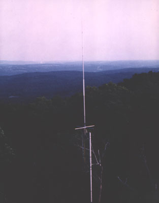
Antenna
During 1983 we did a scientific evaluation of all of the antennas available for the
band that we could find out about, and that we could find a way to finance. Most of
our test antennas ended up on the masts and towers of the participants after the test was
over. This way we weren't just throwing money away. We tested the antennas by
putting them on-the-air on the repeater for a few weeks at a time while driving around the
coverage area of the repeater and seeing what happened. In addition base stations in
the coverage area reported on signal strength and quieting.
We tried the original KLM J-pole, Cushcraft Ringo Ranger, Highgain V2, Hustler G6 and
G7, The G7 was the best RF device by a significant margin. Then, neck and neck
were the G6 and V2. The J-pole was pretty bad and the Ringo Ranger was the worse.
The G6 had the best construction, followed by the KLM J-pole, then the G7, then the
Ringo Ranger and the V2 lost all of it's points with the plastic center insulator.
For cost, the G7 was highest, followed by the G6, then the Ringo Ranger, then the
V2, then the KLM.
We chose the G7 for the repeater antenna. The G6 ended up at my dad's house, the
V2 went to WB2DWD, The KLM became our back-up antenna, and the Ringo Ranger was trashed.
Apparently Cushcraft decided that the radiation angle of 45 degrees UP was
not fashionable and they improved on the problem with the Ranger II a few
years after our test. |
Controller
One of the pieces of resistance that our repeater was to have was a home-brew
microprocessor controlled repeater controller. In December 1982 I built the first
such controller that I'd ever heard. (I had heard rumors of such controllers in
CA). Mine was multitasking and based on a z80 micro.
|
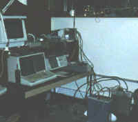 |
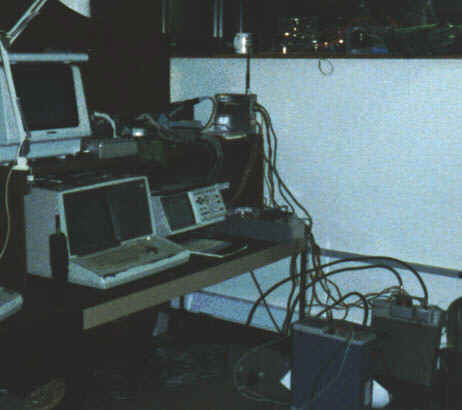
| In picture above and to the right you can see the old HP64000
workstation, a Tek scope, an HP analyzer, a CRT terminal. On the lower right, next
to the scope, you can see a RCA ML1000 440 rig which I was using as a test repeater.
On the upper center is a cast box that was a 220Mhz remote base I was working on.
On the table to the right of the analyzer (below the remote base) you can see
the repeater controller I was building. |
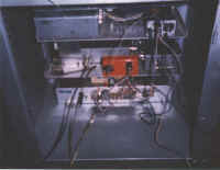
RF
Steve built the RF part. The receiver was based on a Motorola Micor receiver with
a home-made GasFET front end in custom housing. The transmitter was a GE HT as an
exciter, driving a 45 watt hybrid brick to 10 watts (overkill), driving a 80 watt power
amp to 40 watts. With our Hustler G7-144 antenna we saw a 120 miles best case
terrestrial range to a mobile station. |
|
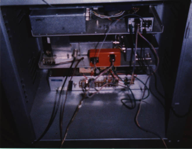
| The rack on the top is the 3rd generation Catfish controller.
The next rack is the transmitter, driver stage and power amp. The next rack
holds the receiver (with GasFET pre-amp on top). Finally the 20 amp continuous duty
power supply. |
| With the help of WB2DWD-Bob, WA2UNN-Clark, and a dozen or so other
volunteers, the repeater was placed on the air in 1982 and maintained for 4 years before
the site was sold and we lost site access. |
|
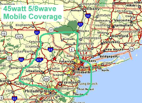
| The Catfish repeater (so named because of it's proximity to the Catfish
Pond) had coverage to 45 watt mobiles which included Wilmington Delaware and high spots in
Albany and Binghamton as well as NYC, Philla, Wilkes-Barre and Scranton. (low spots,
like the Henry Hudson Pkwy in NYC, blacked out coverage outside of 30 miles or so).
There were two other repeaters on our coordinated pair. Both broke coordinator
rules, one in an attempt to drive us off the air, the other for reasons I'm not sure
of. Both repeaters were warts in the coverage of our Catfish repeater even though
the NYC repeater was running 300watts! (A base station could work the Catfish
repeater from all sides of the coverage areas of the other two repeaters.) The
Catfish controller allowed access to stations using 151.4 Hz PL (5Z) which could be
overridden with a simple single digit (5) touch tone. The PL tone requirement would
be re-asserted after a period of 3 minutes of inactivity (determined by 3 minutes of no
> 3 second transmissions) or with a single digit command 6. |
| During our 4 years of tenure we experimented with cross linking to 6m and
220Mhz repeaters, linking to a repeater near Albany NY, and a few other fun sports. The
repeater hardware still lives in more or less it's original configuration. After we
lost the Catfish site, the repeater was located near Allentown PA for another 5 years
before being taken off the air. The hardware is now back in Steve's hands (now KZ1X)
and is still on the air today, as the 145.23 MHz W4UNC repeater, overlooking the campus of
the University of North Carolina at Chapel Hill. Its sister UHF repeater, on 442.15 MHz,
sits high atop a nearby television broadcast tower. Running 1.31 kW ERP, it covers to
mobiles up to 90 miles away, in the spirit of the original Catfish repeater.
While the W4UNC repeater antenna is a new one, it's the same Hustler G-7 model as the
original, shown in the picture above. The duplexer is the original 147.225 MHz WACOM unit,
retuned and still in mint condition after these many years. The RF deck is today a
converted GE MASTR II, built by KR4UB and N4SJW. The controller now in use is also not the
original KA2DEW creation, but an S-COM 7K. However, at random times, it still adds the
word "Catfish" (in Morse code) to the identification message. This is a
puzzlement to many, but tradition must be maintained. |
|